Gridline Property Defaults
In the Project Environment dialog, in [library or project] > Document Production > Gridline Property Defaults, the project administrator can create 'Gridline Property Defaults' configuration objects. The purpose of these objects is to provide common setups for grids that designers insert into drawing views in Plant Modeller documents. Each project should have at least one such configuration object to eliminate the need for designers to set up each grid manually.
Creating gridline property defaults
To provide default settings for grid lines, create a 'Gridline Property Defaults' configuration object in the library database and approve the configuration for use in relevant projects.
Prerequisites
-
At least one Annotation Property Defaults configuration for the visual styling of grid lines. X/Y lines and Z lines can use different configurations.
Do the following:
-
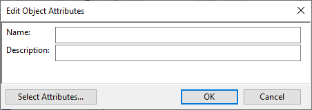
In the Project Environment dialog, browse to [library] > Document Production > Gridline Property Defaults and select New > Gridline Property Defaults. The Edit Object Attributes dialog opens.
-
Enter a descriptive name and, optionally, a description for the configuration, then click OK. The Grid Line Properties dialog opens.
-
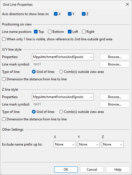
Define the grid line properties.
 Show/hide details
-
Axis directions to show lines in – Select the axis directions for which to add grid lines.
Positioning on view
-
Line name position – Select on which sides of the drawing to show the grid line markings (line names and line-to-line dimensions).
-
Margin from view – Specify whether to add a margin between the grid line markings and the view borders. Enter the value in millimeters; a negative value positions the grid markings within the view.
-
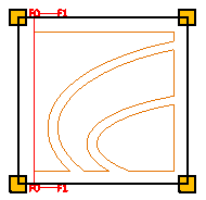
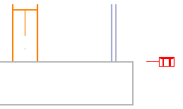
When only 1 line is visible, show… – If selected and the grid area only contains one reference line in X or Y direction, a special marking shows what is the next coordinate reference in that direction, if available. In the example below, only F0 is inside the grid area, so F1 is shown as the next available reference line.
X/Y line style, Z line style
-
Properties – Select the Annotation Property Defaults to use for this grid. The annotation properties define what the grid lines (Line Properties), the grid line names (Text Properties, Symbol Properties), and the line-to-line dimensions (Dimension Properties) look like.
-
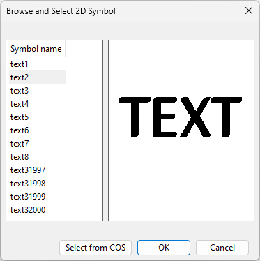
Line mark symbol – Select the 2D Symbol to use for displaying the names of the grid lines.

You can select one of the predefined 2D symbols or a custom symbol that has been stored in COS.
-
Type of line
-
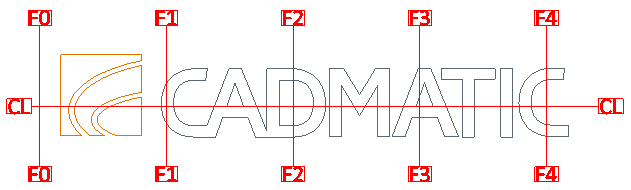
Grid of lines – Select this option to display the grid as lines that extend across the view.
-
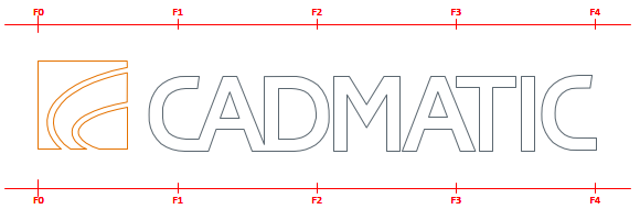
Comb(s) outside view area – Select this option to display comb-type reference line markings on the sides of the view. Every fifth line is slightly longer than the others.
-
Comb(s) – X on centerline if possible – Select this option to display a single X-direction comb along the centerline. If the (Y-direction) centerline is not within the view area, normal top/bottom combs outside the view area are displayed instead.
-
Line labels on outside – Select this option to only display a short line and the reference line's name for Z-direction reference lines.
-
-
Dimension the distance from line to line – Select this option to display the dimensions between the grid lines, on the same side where the line names are displayed.
Other Settings
-
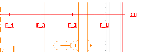
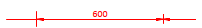
Exclude name prefix up to – You can use this setting to remove an unnecessary naming pattern from the beginning of reference line names, up to and including the first space character or a custom string. For example, setting this to Other: F would remove everything up to and including the F character, as shown below.
-
-
Click OK. The configuration object is now stored in the library.
-
Right-click the configuration object and approve it for use in the project.
Note: If the approval is later removed, any documents that have taken the configuration into use will continue to use it.
Selecting gridline property defaults for drawing views
In the document editor, designers insert grid lines into drawing views with the Grid lines tool. The Grid Line Properties dialog has a field for selecting the gridline configuration to use.